Products / Capacitive Voltage Indicator
OVI+ Series
Orion EE OVI+ Series Capacitive Voltage Indicators
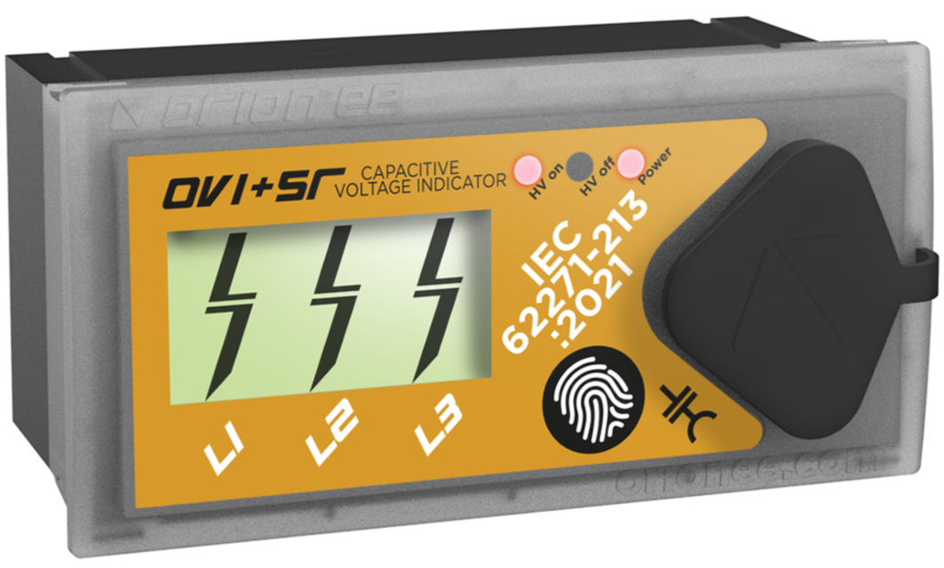
When LCD-based voltage presence indication is needed in MV switchgear, we specify the OVI+ Series. OVI+ covers compact local indication, while OVI+R, OVI+S and OVI+SR add relay contacts, display test and operation-safe signalling options according to the project requirement.
About this product
Selecting the OVI+ Series model
The OVI+ Series is designed for IEC 62271-213:2021 compliant voltage presence and absence indication in MV switchgear. Use OVI+ for compact LCD indication, OVI+R when a relay contact is required, OVI+S when display test and overvoltage indication are needed, and OVI+SR when display test and two independent change-over contacts are required in the same unit.
RFQ information
To select the correct unit, the C1 coupling electrode capacitance, cable type and length, cable unit capacitance and nominal voltage Un must be checked together. The C2 value is not selected as a standalone catalogue choice.
Model Selection
| Model | Positioning | Display | Relay / Contact Output | Test Function | Auxiliary Power Supply | Use when |
|---|---|---|---|---|---|---|
| OVI+ | Compact LCD voltage indicator | 3-phase LCD display | Not applicable | Not applicable | Not applicable for voltage detection | LCD-based local voltage presence indication is required without relay output or display test function |
| OVI+R | LCD voltage indicator with status contact | 3-phase LCD display | 1 change-over contact | Not applicable | 24-230 V AC/DC | Voltage presence indication must also provide a relay contact signal for SCADA, external lamp or interlocking |
| OVI+S | Compact LCD voltage indicator with display test and overvoltage indication | 3-phase LCD with bigger screen | Not applicable | Integrated display test without auxiliary power | Not applicable for voltage detection | Display test, two-stage indication and overvoltage indication are required without relay output |
| OVI+SR | LCD voltage indicator with display test and dual status contacts | 3-phase LCD with bigger screen | 2 change-over contacts | Integrated display test without auxiliary power | 24-230 V AC/DC | Display test, overvoltage indication and two independent status contacts are required together |
Model-Based Technical Comparison
| Model | Display | LRM Interface | Two-stage Indication | Overvoltage Indication | Integrated Display Test | Relay / Contact Output | Contact Status LED | Auxiliary Power Supply | Power Consumption | Contact Rating | Connection Leads | AMP Connection | Variable C2 Module | Protection Class | Cutout Size | Weight |
|---|---|---|---|---|---|---|---|---|---|---|---|---|---|---|---|---|
| OVI+ | 3-phase LCD display | LRM | Not applicable | Not applicable | Not applicable | Not applicable | Not applicable | Not applicable for voltage detection | Not applicable | Not applicable | 4.8 x 0.8 mm faston terminal and AMP | Optional | Optional | IK07 / IP54 (Front) | 92 x 45 mm | 75 g, or 95 g with variable C2 module |
| OVI+R | 3-phase LCD display | LRM | Not applicable | Not applicable | Not applicable | 1 change-over contact | 1 LED indicator for power supply | 24-230 V AC/DC | Less than 2 W | 5 A 250 VAC or 5 A 30 VDC with resistive load | 4.8 x 0.8 mm faston terminal and AMP | 2x AMP optional | Optional | IK07 / IP54 (Front) | 92 x 45 mm | 160 g max. |
| OVI+S | 3-phase LCD with bigger screen | LRM | Yes | Yes | Yes, without auxiliary power | Not applicable | Not applicable | Not applicable for voltage detection | Not applicable | Not applicable | 4.8 x 0.8 mm faston terminal and AMP plug | 2x AMP optional | Optional | IK07 / IP54 (Front) | 92 x 45 mm | 75 g, or 95 g with variable C2 module |
| OVI+SR | 3-phase LCD with bigger screen | LRM | Yes | Yes | Yes, without auxiliary power | 2 change-over contacts | 2 LEDs for contact status and 1 LED for power supply | 24-230 V AC/DC | Less than 2 W | 5 A 250 VAC or 5 A 30 VDC with resistive load | 4.8 x 0.8 mm faston terminal | 2x AMP optional | Optional | IK07 / IP54 (Front) | 92 x 45 mm | 165 g max. |
Mechanical Dimensions
| Model | Front Size | Panel Cutout | Installation Depth | Body Type | Weight |
|---|---|---|---|---|---|
| OVI+ | 95 x 48 mm | 92 x 45 mm | 23.35 mm | Compact body | 75 g, or 95 g with variable C2 module |
| OVI+R | 95 x 48 mm | 92 x 45 mm | 63.5 mm max. | Relay-output body | 160 g max. |
| OVI+S | 95 x 48 mm | 92 x 45 mm | 23.35 mm | Compact body with display test | 75 g, or 95 g with variable C2 module |
| OVI+SR | 95 x 48 mm | 92 x 45 mm | 63.5 mm max. | Relay-output body with display test | 165 g max. |
Common Technical Specifications
| Parameter | Value |
|---|---|
| Applicable Standard | IEC 62271-213:2021 |
| Interface | LRM |
| Application | Voltage presence and absence indication in MV equipment |
LCD Indication Status
| LCD Indication | Normal Operation Definition | Voltage Condition | C2 Module Condition | Test Button Result |
|---|---|---|---|---|
| Overvoltage | Overvoltage | U > 120% Un | C2 module < C2 min. | Test OK |
| Nominal voltage present | Nominal voltage present | U > 45% Un | C2 module correct | Error |
| Voltage present | Voltage present | 10% Un < U < 45% Un | C2 module > C2 max. | Error |
| No indication | Voltage not present | U < 10% Un | C2 module >> C2 max. | Error |
Relay / Contact Logic
| Model / Relay | Terminals | Auxiliary Power | Voltage Absent State | Voltage Present State |
|---|---|---|---|---|
| Relay 1 | 5 = NO, 4 = COM, 3 = NC, 2 = +Vaux, 1 = -Vaux | Contacts require auxiliary power to operate. | All phases < 10% Un | At least one phase > 45% Un |
| Relay 1 | 8 = NO1, 7 = COM1, 6 = NC1 | Contacts require auxiliary power to operate. | All phases < 10% Un | At least one phase > 45% Un |
| Relay 2 | 5 = NO2, 4 = COM2, 3 = NC2 | Contacts require auxiliary power to operate. | Defined by selected Type A or Type B contact mode | Defined by selected Type A or Type B contact mode |
Type A / Type B Contact Modes
| Mode | Definition | Safe Operation Note |
|---|---|---|
| Type A | Standard contact mode. With auxiliary power present, the contact follows the voltage-absent and voltage-present thresholds. | If auxiliary power is lost, the contact cannot actively signal the voltage-present safe position. |
| Type B | Operation-safe contact mode. If auxiliary power is lost, the contact takes the voltage-present position. | This prevents unsafe operation by treating loss of auxiliary power as a live-voltage condition. |
Required Data for Order
| Required Data for Order |
|---|
| Capacitance of coupling electrode C1 |
| Cable type, length and unit capacitance |
| Nominal voltage Un |
C2 Capacitance Options
| C2 Capacitance Options |
|---|
| 1, 1.2, 1.5, 1.8, 2.2, 2.7, 3.3, 3.9 nF |
| 4.7, 5.6, 6.8, 8.2, 10, 12, 15, 18, 22 nF |
| 27, 33, 39, 47, 56, 68, 82, 100 nF |
Request a Consultation
Send us your project requirements and we will get back to you.