Sepam Series
Sepam Protection Relays and Modernization
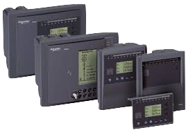
When an existing Sepam relay needs maintenance, spare parts, or modernization rather than being part of a new installation, this is where we help. Sepam S, M, T, G, and B cover feeder, motor, transformer, generator, and busbar/capacitor bank applications across existing MV installations, and we evaluate the active protection functions, I/O, communication, and panel dimensions of your specific relay to recommend a suitable PowerLogic P1, P3, or P5 replacement.
About this product
Schneider Electric Sepam Series covers application families used for feeder, motor, power transformer, generator, busbar, and capacitor bank protection in existing MV installations. The purpose of this page is not to position Sepam as a current product for new projects, but to guide maintenance, spare part, and modernization requirements for the installed base.
Product status: Although part of the Sepam range has reached the end of its commercial life, maintenance, spare part, and modernization requirements remain in existing installations. Forvis Trade evaluates the protection functions, input and output arrangement, communication infrastructure, and panel dimensions of the existing Sepam relay to develop a replacement solution using a suitable PowerLogic P1 - P3 - P5 series relay.
Application families
- Sepam S: Feeder and substation protection
- Sepam M: Motor protection
- Sepam T: Distribution and power transformer protection
- Sepam G: Generator protection
- Sepam B: Busbar and capacitor bank protection
These family names are not sufficient on their own for replacement selection. Different hardware, function, I/O, and communication configurations may exist within the same Sepam family. The exact model reference and installed configuration must be verified on site.
Modernization approach
PowerLogic P1 can be considered for essential overcurrent, earth fault, voltage, and frequency applications. PowerLogic P3 can be considered for standard feeder, motor, and transformer applications. PowerLogic P5 can be considered where advanced protection, differential functions, high I/O capacity, or complex automation is required. Final selection must be based on active protection functions and installation requirements rather than the old Sepam model name alone.
Sepam modernization may include relay selection, function mapping, mechanical adaptation, wiring modifications, setting migration, communication integration, testing, and commissioning.
Information required before replacement
- Complete Sepam model and order reference
- Active protection functions and settings file
- CT and VT ratios and connection diagram
- Digital inputs, relay outputs, and external modules
- RTD and temperature monitoring connections
- Communication protocol and SCADA data map
- Circuit breaker control and interlocking logic
- Panel cut-out dimensions and existing wiring
Share the model, application, and existing connection details to evaluate modernization of your Sepam relay with the PowerLogic P1 - P3 - P5 series.
Technical Specifications
| Applications | Feeder, motor, transformer, generator, busbar, and capacitor bank protection |
| Platform | Legacy Sepam application families |
| Communication | Model dependent; verify the exact relay reference |
| IEC 61850 | Available only on selected later Sepam ranges |
| Sensor Support | Conventional CT/VT; model dependent |
| Arc-Flash Protection | Not specified |
| Mounting | Flush-mounted; dimensions vary by model and HMI |
| Engineering Software | Legacy Sepam engineering tools; verify by model |
| Product Status | Legacy family; commercial status varies by model |
Sepam Application Families
| Sepam Family | Main application | Typical protection scope | Critical modernization information |
|---|---|---|---|
| Sepam S | Feeder and substation protection | Overcurrent, earth fault, directional, voltage, frequency, breaker control, and loss-of-mains functions depending on model | Full model, active functions, breaker-control logic, I/O and communication |
| Sepam M | Motor protection | Thermal, starting, locked-rotor, unbalance, temperature, and motor differential functions depending on model | Motor data, RTD modules, starting method and differential scope |
| Sepam T | Transformer protection | Overcurrent, earth fault, Buchholz, temperature, restricted earth fault, and transformer differential functions depending on model | Number of windings, vector group, CT ratios, RTD and external protection inputs |
| Sepam G | Generator protection | Power, excitation, negative-sequence, frequency, generator differential, and unit differential functions depending on model | Generator data, CT/VT arrangement, neutral arrangement and differential scope |
| Sepam B | Busbar and capacitor bank protection | Busbar voltage and frequency supervision, incomer and bus-coupler applications, capacitor overcurrent, and unbalance protection depending on model | Busbar arrangement, coupler logic, capacitor connection and active functions |
Protection Functions
| Sepam Family | Protection scope | Main functions |
|---|---|---|
| Sepam S | Feeder and substation protection | 50/51, 50N/51N, 67, 67N, 27, 59, 81, 81R (model dependent) |
| Sepam M | Motor protection | 37, 46, 48/51LR, 49, 50/51, 66, 87M (model dependent) |
| Sepam T | Transformer protection | 26/63, 49, 50/51, 50N/51N, 64REF, 87T (model dependent) |
| Sepam G | Generator protection | 32, 40, 46, 50/51, 59, 81, 81R, 87G (model dependent) |
| Sepam B | Busbar and capacitor bank protection | 27, 50/51, 51C, 59, 59C, 81, 81R (model dependent) |
Initial Modernization Assessment
| Existing application | Platforms to evaluate first | Selection criteria |
|---|---|---|
| Basic feeder protection | P1F or P3U20 | Directional functions, I/O, communication and autoreclosing requirements |
| Directional or IEC 61850 feeder | P3U30, P3F30 or P5F30 | CT/VT arrangement, IEC 61850, GOOSE, arc flash and I/O capacity |
| Basic voltage and frequency | P1V or P5V20 | VT connection, frequency functions, I/O and communication |
| Motor | P3M30, P3M32, P5M30 or P7 Motor | Motor rating, starting, RTD, speed sensing and differential requirements |
| Transformer | P3T32, P5T30 or P7 Transformer | Number of windings, vector group, CT ratios, REF and differential scope |
| Generator | P3G30, P3G32 or P7 Generator | Power, excitation, stator earth fault, differential and synchrocheck |
| Line or cable differential | P3L30, P5L30 or P7 Line Differential | Line length, communication channel, distance backup and charging current |
| Busbar differential | P7 Busbar Differential | Busbar arrangement, number of bays, CT zones and breaker-failure logic |
| Extensive bay control or digital substation | P7 Bay Control Unit or P7 SAMU | I/O capacity, IEC 61850 sampled values and network redundancy |
Request a Consultation
Send us your project requirements and we will get back to you.